Across the globe, in the oil and gas industry, there is continued importance on integrity management of ageing assets and maintaining the longevity of pipelines and structures that are reaching the end of their design life. In most regions, these pipelines may only be operated beyond their intended design life if an extension study has been conducted and approved by stakeholders.
In recent years, the idea of continuing use beyond a pipeline’s design life has become increasingly accepted. This could be considered for example, due to a new field development that needs to be tied back to an existing pipeline, or simply that there are still reserves to be recovered after the expiration of production asset lifetimes.
Corrosion damage is the main concern with ageing pipelines that dominates any plans to extend their life cycle. Corrosion is the breakdown of the parent material due primarily to electrochemical processes where there is an exchange of electrons between two materials. Corrosion has the potential to reduce a product’s design life by premature degradation.
The rates of attack and severity of corrosion will vary depending on certain influencing factors. Typical corrosion mechanisms include uniform corrosion, stress corrosion cracking, and pitting corrosion.
Other scenarios that could cause integrity concerns are:
- Third party: This is more a concern in shallower waters and can be the result of trawl/anchor damage to a pipeline.
- Mechanical: These can be related to the manufacturing or installation process of the pipeline.
- Natural hazards: Wave action and currents can cause scouring and accentuate free span issues.
Although pipelines are designed and manufactured in accordance with design codes, unanticipated changes in the environment in which the assets operate can result in unexpected corrosion damage. Moreover, the combined effects of corrosion and mechanical damage, together with environmentally assisted material damage can result in unexpected failures.
Given the typical lengths of subsea pipelines, most operators would consider an internal inspection method to use as the basis for the life extension study. These are conducted utilising intelligent in-line inspection (ILI) tools that provide comprehensive coverage over the full length of the pipeline. In some cases, it is not possible to carry out an ILI inspection due to reduced product flows and the absence of launch and receive facilities etc. In these cases, tethered or bi-directional tools may be required.
These options, however, require the pipeline to be taken out of service for the duration of the inspection with associated production losses.
Pipeline targeted inspections online
In this situation, an operator will need to consider an alternate means of inspection of the pipeline. Most operators would consider the use of sampling or targeted inspection of selected locations along the length of the pipeline following a detailed corrosion risk assessment (CRA). The locations are selected on the basis of the highest susceptibility to degradation as determined by the CRA.
Not all circumstances are predictable, but many are. Examples include low points in the pipeline where water may collect, cooler locations where condensation may occur, or locations where inhibitors may have been ineffective and are no longer protecting the internal surfaces of the pipeline etc.
However, when conducting an external sampling or targeted inspection, any access restrictions at the selected locations need to be assessed. Consideration should be given to whether the pipeline is buried, as well as the external coating type, as this can prove challenging to inspect through with certain inspection technologies. Removal of the coating could be carefully considered,
however, this will impact the life-extension study, as removal of insulation/coating will affect the pipeline protection and condition.
Sonomatic has developed an exciting new inspection technology that enables inspection to be conducted through certain challenging subsea coatings where conventional ultrasonic is ineffective. Dynamic response spectroscopy (DRS) is an innovative ultrasonic inspection technique for corrosion mapping through attenuative coatings.
A custom DRS probe excites the steel with a range of low ultrasonic frequencies, which pass easily through the challenging coatings (such as neoprene, polypropylene/polyethylene, composite wrap repairs, and Thermotite). The steel responds, vibrating at natural frequencies related to its thickness profile. Using advanced algorithms, these frequencies are extracted from the returning signal at each location and used to determine the steel thickness.
Due to the reduced coverage achievable by conducting externally applied technologies, typically at a tiny fraction of the total line, the purpose of the inspection is not to locate all the degradation present in each pipeline, or even to confidently locate the worst-case location. The actual purpose is to gather sufficient information to underpin with confidence the assumptions of the CRA study.
Any inspection technology considered needs to provide data that will offer the accuracies of inspection that will be suitable to use as part of the life extension study. Inspection performance requirements, with respect to the accuracy of measurement and probability of
detection (POD), would need to be defined to ensure a low coverage inspection will provide a sufficient basis for statistical analysis of data.
POD is key when performing a life extension study. A key factor when considering POD is the accuracy of the measurement and scan resolution, particularly for small diameter pits. Trials conducted by Sonomatic, supported by inspection modelling to estimate POD values for a 1 mm x 4 mm resolution identified that POD was greater than 90% for 1 mm deep flaws with an aspect ratio of 5. Sonomatic has supported their clients by providing the following services in support of the evaluation of unpiggable pipelines:
- Bayesian statistical analysis for planning and evaluation of compliance inspections for dry gas lines where the purpose of the inspection is to validate the absence of corrosion.
- Sampling inspection scheme development and evaluation of results for lines where the conditions are sufficiently homogeneous to allow a sufficient quantification of degradation characteristics based on small coverage.
- Statistical simulation to assess the effectiveness of sampling options and to evaluate the reliability of the results. This includes consideration of both quantified sampling and screening type approaches.
- Planning and evaluation based on direct assessment methods, for example, ICDA or ECDA.
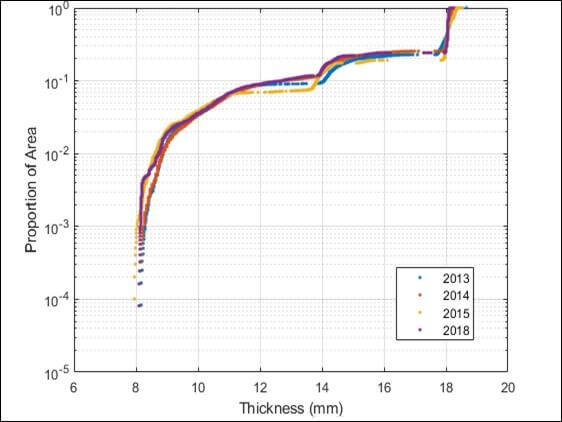
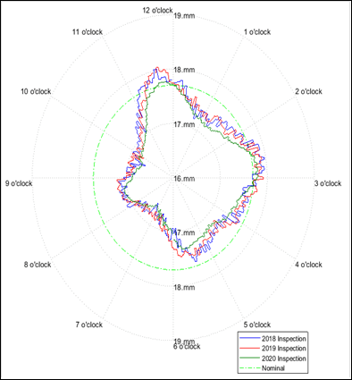
An advanced integrity services capability incorporating statistical processes adds value to the inspection data. Critical comparisons between repeat inspections with high degrees of precision, circumferential profiling of the external surfaces of pipelines, and extrapolation of collected data over un-inspected areas are examples.
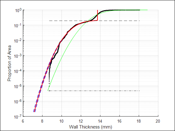
Thickness distribution plots are graphical representations of measured thicknesses plotted against the proportion of area on a logarithmic scale. These plots can be highly informative in terms of portraying the actual corrosion behaviour. Often, historic corrosion behaviour can be extracted. This is highly informative in terms of correlating observed corrosion behaviour to that predicted through the CRA. (Figure 2).
It can be seen that the value is far beyond the concept of conventional ultrasonic corrosion mapping that typically generates minimum, maximum, and average thicknesses. The adage ‘garbage in, garbage out’ applies and an integrated, appropriately controlled inspection generates the quality of source data that is used to maximum effect in the integrity assessment.
Pipeline screening to maximise coverage
It is not a realistic option to conduct full-length coverage of a pipeline using externally applied inspection technologies such as 0-degree corrosion mapping. This would be very costly and time-consuming due not only to the impractical duration of the inspection itself, but also the implications of dredging, weight-coat, and coating removal.
From an operator’s perspective, it would be more desirable and cost-effective, where possible, to use a less invasive screening inspection technique. Screening techniques such as medium-range horizontally polarised guided shear waves introduced by electromagnetic acoustical transducers (EMATs) and/or Multiskip using shear wave pulse echo probes in a pitch/catch mode of the operation, make screening of the pipeline possible and can provide a more global perspective of the pipeline, suggesting which area may require additional attention.
The optimum approach to inspection will depend on the nature of the potential degradation. In some cases, a screening approach will be appropriate. Screening methods typically provide for higher coverage; however, these techniques provide ‘qualitative’ results and will only offer a general understanding of wall loss in a particular area (typically a coarse percentage of wall loss at each location).
They will alert the operator of the need for further ‘quantitative’ inspection being required in that location to obtain accurate wall thickness measurements for further analysis. The focus of screening is therefore often on providing assurance that the inspection identifies the most severe degradation or at least regions representative thereof.
The inspection planning process for unpiggable pipelines has the aim of identifying the most effective approach for each situation and ensuring the inspection meets the integrity requirements.
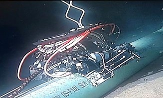
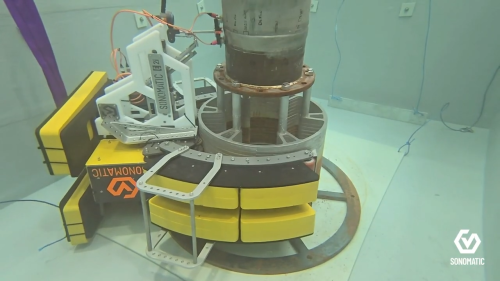
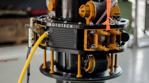
The bespoke Sonomatic MAG-ST crawler (Figure 3) has been utilised on recent campaigns to deploy screening techniques such as EMAT/Multiskip, on multiple pipelines at <1000 m water depth. These lines were not designed for in-line inspection and had been in service for many years, therefore an assessment of their condition was necessary. The inspection to assess their condition had to be performed using external direct assessment methods.
Differing diameters and external coating types can result in the inspection being challenging and may require the need for both screening techniques depending on the pipeline specifics. Typically, in one 24 hr offshore period, approximately 320m of pipeline can be screened with these techniques, resulting in a total of approximately 10 km of pipeline inspection on a 2 – 3-week offshore inspection campaign.
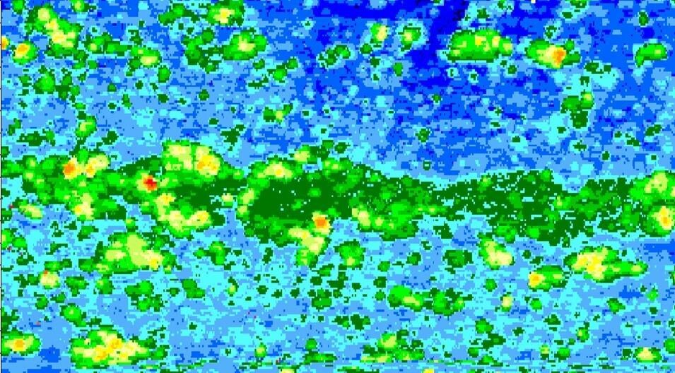
Support technologies are required for follow up inspections at areas of degradation of concern as identified by the screening inspection. These follow up techniques have the ability to quantify the depth and characteristics of the degradation in detail, supporting the CRA process and allowing fitness for service assessment to be performed. Ultrasonic corrosion maps, or C-scans (Figure 1) can be exported in .csv file format directly to a finite element model for stress distribution analysis.
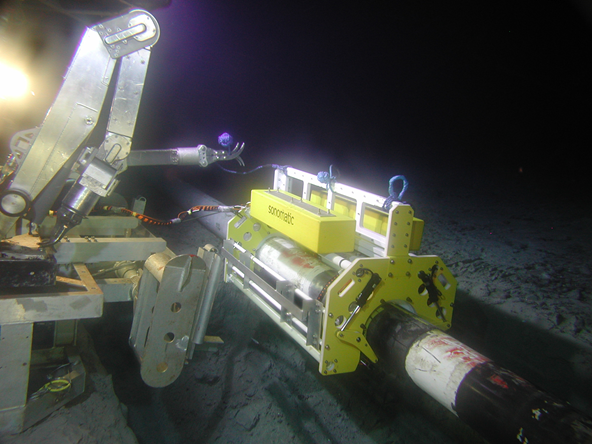
Sonomatic utilises the ROV-iT scanner (Figure 4) for such inspections where quantitative results are required from a specific location. The ROV-iT has been utilised extensively since 2012 for subsea inspection of un-piggable pipelines down to water depths of 1750 m to
date (pressure tested to 3000 m).
The scanners have the capacity to inspect pipelines with outer diameters from 6 in. up to 30 in. The two smaller units are deployed over the side of the ROVSV or through the moonpool, attached to the front of most modern work class ROVs. However, the larger ROV-iT 30 must be deployed subsea in a work basket, and the ROV will ‘hot stab’ into the scanner for power and comms operations.

